

12' Cincinnati AF x 10FT 350 Ton Hydraulic Press Brake w/Updated CNC Controller, Backguage & Dies
Have one to sell?
ConditionUsed
1 available
$59,500.00 USD
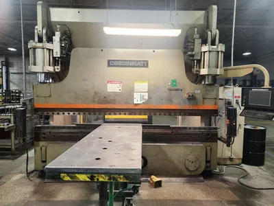
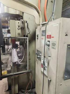
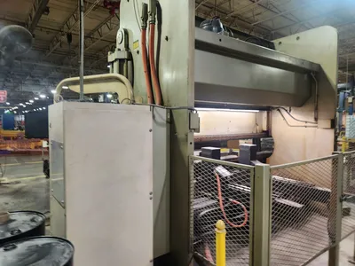
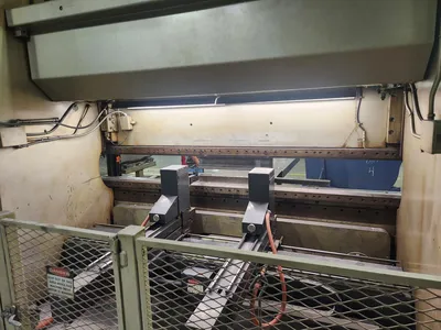
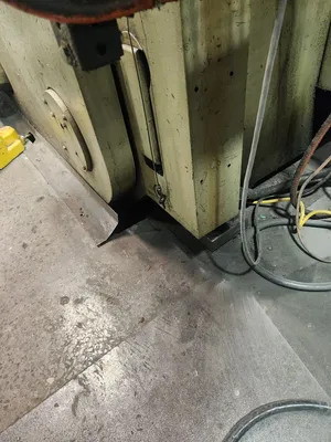
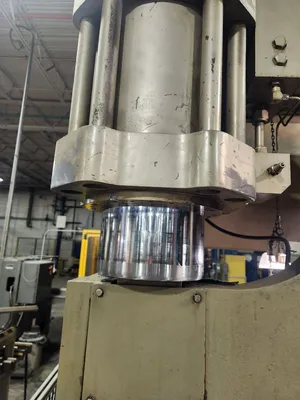
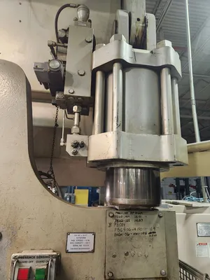
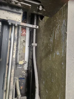
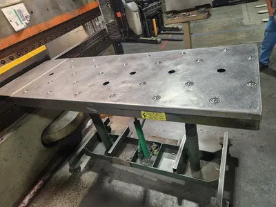
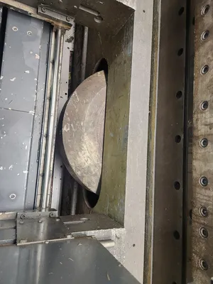
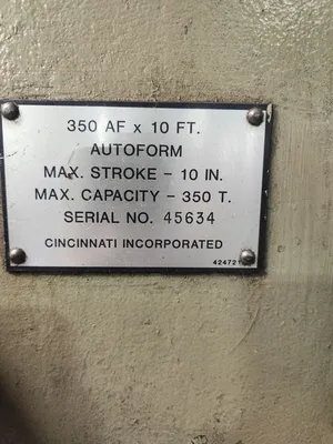
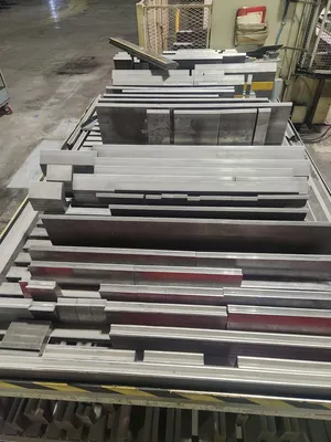
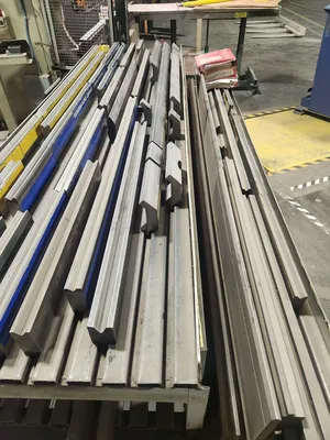
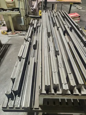
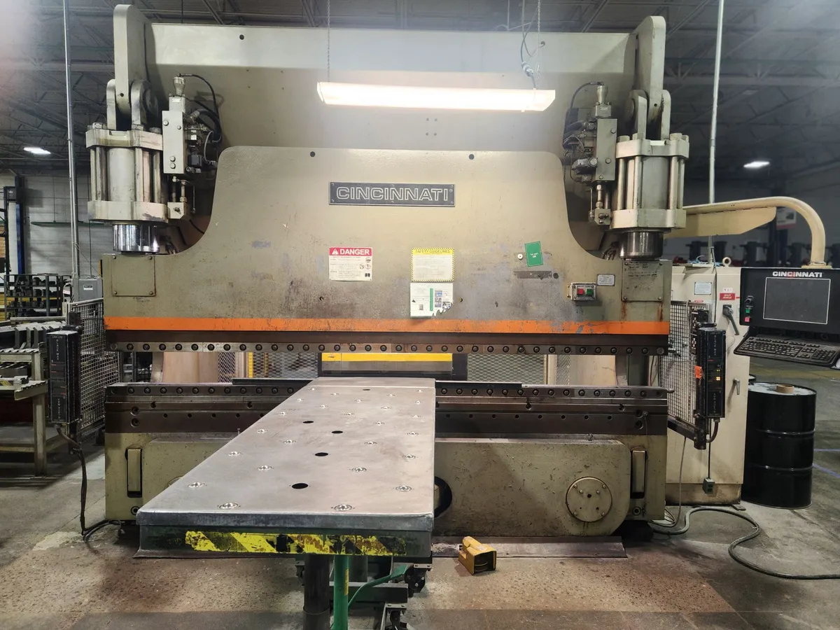
Cincinnati Press Brake, Model 350 AF X 10 FT.,
Serial Number 45634,
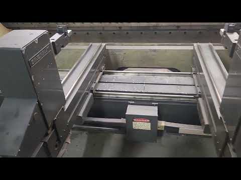
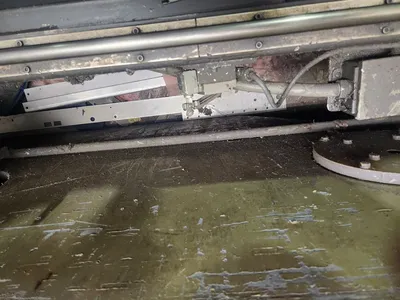
Back Gauge
350 Ton Max Stroke 10 Inches
Additional Options: Foot And Palm Button Controls
Power 460 Volts / 60 Hertz / 39.7 Amps / 3 Phase
The Cincinnati Model 350 AF x 10 FT is a heavy-duty hydraulic press brake featuring a 350-ton capacity, an overall bed length of 12 feet (144 inches), and 10 feet 6 inches (126 inches) of clearance between the side housings.
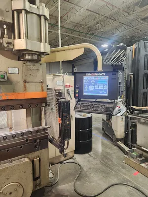
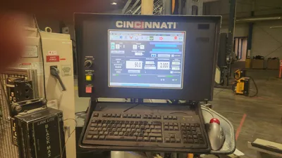
Equipped with a standard 10-inch stroke, a 10-inch throat depth, and an 18-inch maximum daylight opening, this machine utilizes an Adaptive AutoForm CNC control system to deliver high-precision metal fabrication and bending performance.
Powered by a 40 HP motor, the assembly features approximate physical dimensions of 16' L x 7' W x 12' H and weighs roughly 44,000 lbs. Base packages typically include electrical foot pedals and dual palm button controls.
The Cincinnati Model 350 AF x 10 FT (often referenced as a 350-ton hydraulic press brake with a 12-foot overall bed/ram length) features the following core specifications:
Key Specifications
• Tonnage Capacity: 350 Tons
• Overall Length of Bed and Ram: 12 feet (144 inches)
• Distance Between Housings: 10 feet 6 inches (126 inches)
• Max Stroke of Ram: 10 inches
• Open Height: 17 inches – 18 inches (depending on configuration)
• Closed Height: Varies by setup (~8 inches)
• Throat Depth: 10 inches
• Control Type: Originally equipped with Cincinnati Auto Form (AF) control
Independent Drive Assembly (Multi-Axis & 5-Axis/6-Axis)
Rather than a single rigid backgauge bar, the AutoForm system utilizes two independent gage drive assemblies.
• Independent Motion: Each of the two drive assemblies can be independently programmed and positioned.
• Advanced Multi-Axis Setup: In higher-end configurations (such as a 5-axis or 6-axis setup), the system can control independent X-axis depth for both assemblies (often labeled X1 / X2) to handle asymmetric or tapered flange bending.
• Gage Fingers: The fingers attach to a gage bar or individual carriers and feature specialized upper/lower orientation adjustments depending on your 5-axis operation settings.
Machine Dimensions: Roughly 16 ft. (length) x 7 ft. (width) x 12 ft. (height)
• Approximate Weight: 44,000 lbs
Imperial
| Tonnage | 350 T |
| Type | HYD |
| Overall Length | 12' |
| Between Housings | 10' |
| Stroke | 10" |
| # Axis | 5 |
| Control | CNC (CINCINNATI BASEFORM CNC CONTROLLER) |
| Dimensions | 16' x 7' x 12' |
| Weight | 44000 |
Cincinnati Press Brake, Model 350 AF X 10 FT.,
Serial Number 45634,
Back Gauge
350 Ton Max Stroke 10 Inches
Additional Options: Foot And Palm Button Controls
Power 460 Volts / 60 Hertz / 39.7 Amps / 3 Phase
The Cincinnati Model 350 AF x 10 FT is a heavy-duty hydraulic press brake featuring a 350-ton capacity, an overall bed length of 12 feet (144 inches), and 10 feet 6 inches (126 inches) of clearance between the side housings.
Equipped with a standard 10-inch stroke, a 10-inch throat depth, and an 18-inch maximum daylight opening, this machine utilizes an Adaptive AutoForm CNC control system to deliver high-precision metal fabrication and bending performance.
Powered by a 40 HP motor, the assembly features approximate physical dimensions of 16' L x 7' W x 12' H and weighs roughly 44,000 lbs. Base packages typically include electrical foot pedals and dual palm button controls.
The Cincinnati Model 350 AF x 10 FT (often referenced as a 350-ton hydraulic press brake with a 12-foot overall bed/ram length) features the following core specifications:
Key Specifications
• Tonnage Capacity: 350 Tons
• Overall Length of Bed and Ram: 12 feet (144 inches)
• Distance Between Housings: 10 feet 6 inches (126 inches)
• Max Stroke of Ram: 10 inches
• Open Height: 17 inches – 18 inches (depending on configuration)
• Closed Height: Varies by setup (~8 inches)
• Throat Depth: 10 inches
• Control Type: Originally equipped with Cincinnati Auto Form (AF) control
Independent Drive Assembly (Multi-Axis & 5-Axis/6-Axis)
Rather than a single rigid backgauge bar, the AutoForm system utilizes two independent gage drive assemblies.
• Independent Motion: Each of the two drive assemblies can be independently programmed and positioned.
• Advanced Multi-Axis Setup: In higher-end configurations (such as a 5-axis or 6-axis setup), the system can control independent X-axis depth for both assemblies (often labeled X1 / X2) to handle asymmetric or tapered flange bending.
• Gage Fingers: The fingers attach to a gage bar or individual carriers and feature specialized upper/lower orientation adjustments depending on your 5-axis operation settings.
Machine Dimensions: Roughly 16 ft. (length) x 7 ft. (width) x 12 ft. (height)
• Approximate Weight: 44,000 lbs
We use cookies to improve your experience. Privacy Policy.